How thermal bridging affects energy use?
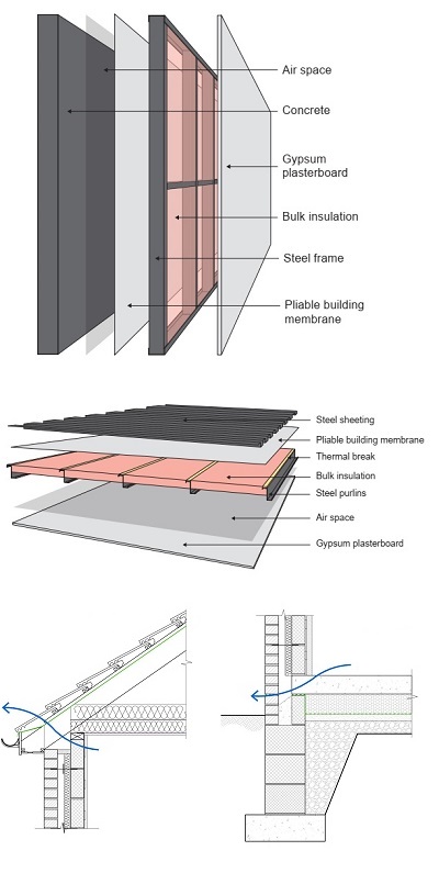
In a roof or wall construction, where some areas have low thermal conductivity materials such as insulation and other areas have high thermal conductivity materials such as stud framing, thermal bridging occurs. This means heat can easily flow through the high thermal conductivity section (i.e. with the lowest thermal resistance) to/from the outdoors. Thermal bridging results in an overall reduction in the thermal resistance of the building fabric. This phenomenon greatly contributes to the energy efficiency of the building. Thermal bridging increases energy demand, makes the building vulnerable to condensation and creates a less thermal comfortable environment to live in. Thermal bridging must be addressed conducting Section J reports for commercial buildings. Find out more…

When is thermal bridging significant?
For a typical wall construction where no insulation is added between the wall studs or roof rafters/joists, thermal bridging is neglected. Also for timber walls or roofs with a modest amount of insulation, the thermal bridging effect is arguably not significant. However, in cases where you have metal walls/roofs or timber walls/roofs with thick insulation, the negative effect of thermal bridging must be calculated which results in the actual Total R-value of the wall/roof construction. This is how we do it here at Energy Compliance Consultants!
For commercial buildings as described in NCC Vol 1.0 and using verification methods like JV2, JV3 and NABERS, effect of thermal bridging must be fully taken into account,
For residential buildings however, only R0.2 thermal break as a treatment for thermal bridging are mandated for steel frame construction only in Part 3.12 DTS provisions. Therefore, thermal bridging is not necessary to be accounted for while performing VURB compliance method.

How to calculate thermal bridging?
There are four steps for the calculation of the negative effect of thermal bridging:
1- Determine the bridged layer
The bridge layer is a non-uniformity in a continuous material; for example, if the insulation is installed between the metal purlins, the insulation uniformity is lost because it is bridged by metal purlins. According to NZS 4214, a bridged layer is not bounded by an air space; therefore, if the wall consists of air space with a sufficient thickness so it could act as a thermal resistant layer, then the airspace must be included within the thermally bridged layer. Generally, if there is at least 20mm air adjacent to the insulation in a bridged layer, then the thermal resistance of air (R0.17) must be added to the thermal resistance of insulation.
2- Determine the portion of each parallel material
You must determine what portion of the wall consists of the high conductivity material such as metal frames. For example, a 3m2 wall has insulation with an area of 2.7m2 that is bridged by metal stud frames, the portion of insulation is 2.7/3=90% and we also have a 10% metal stud area.
3- Determine the R-value of each parallel material
To calculate the thermal resistance (R-value) of a material, divide its thickness by its thermal conductivity. For example, a 90mm thick timber batten has 0.09/0.1=0.9 m2K/W thermal resistance. Keep in mind the addition of air space resistance if available above each parallel layer.
4- Calculate the net R-value of the bridged layer
The net R-value of the bridged layer can then be calculated as below:

Where Rb is bridged layer net R-value, f1 and f2 are consecutive portions (%) of each parallel layer, R1 and R2 are consecutive R-values of each parallel layer (i.e. insulation and bridging medium)
How to mitigate thermal bridging?
there are four major contributing factors to the mitigation of the negative thermal bridging effect. These factors are briefly discussed below:
Framing material
The selection of framing material for wall or roof construction depends on many factors like bearing load or fire hazard. The use of timber stud walls is better than metal stud frames as the thermal conductivity of steel is 400 times more than timber (47.4 to 0.1 W/m2K). Concrete walls could be ideal to significantly reduce the thermal bridging effect where a continuous and rigid insulation panel (e.g. insulated plasterboards) is used. This is also favourable for a suspended concrete floor as well as concrete walls or roofs. Complete mitigation of the thermal bridging effect can be obtained using fully continuous structural systems like Structural Insulated Panels (SIPs).
Framing dimensions
Thermal bridging depends on the width, depth and span of the framing elements. The smaller the width of the element, the more insulation could sit between the two framing elements. Increasing the depth of framing increases its thermal resistance while allowing to have thicker insulations. Perhaps the most important factor of all is the framing span. The more the framing span, the lesser the thermal bridging effect. Increasing the framing span simply means more room for insulation and less area occupied by framing materials. Thickness is also important for metal construction. The lesser the thickness, the narrower the pathway for the heat to flow.
Insulation
If there is no insulation installed between the wall or roof frames, then no thermal bridging occurs (with an exception of external wall/roof cladding and internal wall lining directly attached to metal frames). With a modest amount of insulation in timber wall/roof construction (less than R2.0), the negative effect of thermal bridging is arguably small. The negative effect increases with the thickness of the insulation and the thicker the insulation gets, the more the thermal bridging effect increases exponentially. Hence, you get to a spot where even getting from R6.0 to R8.0 (unrealistic) won’t add but a couple of decimal numbers to the roof Total R-value.
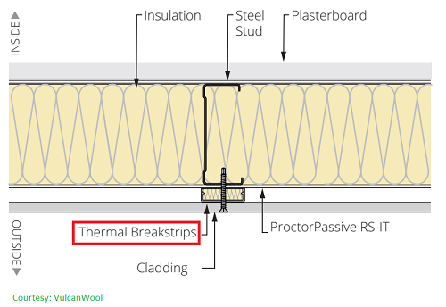
Thermal Break
A thermal break is a piece of material with a low thermal conductance that is attached to the end of each framing material. Thermal break acts as a heat block to reduce the heat flow through the high conducting framing elements. Thermal break material consists of wood, EPS, Rockwool, rigid PIR and many more. The addition of thermal break also adds an air gap above the insulation with an added resistance. Thermal breaks are the most effective way for the mitigation of thermal bridging and are widely used across the commercial section. There are mandatory regulations for energy efficiency or the buildings in Australia and are described below.
If there are several construction options, its better to have an energy consultant navigate through options for a more energy efficient design.
What are the mandatory provisions for the treatment of thermal bridging?
Residential buildings
The residential section and its mandatory provisions for thermal breaks are described in:
- NCC Vol 1.0, Section J, Parts J0.4 & J0.5, for Class 2 & Class 4 part of the building.
- NCC Vol 2.0, Part 3.12.1.2 (c) & Part 3.12.1.4 (d), for Class 1a, Class 1b and Conditioned Class 10a.
More on building classes…
As the proposed solution is the same in both volumes, we only cite the provisions for roof thermal breaks according to NCC Vol 1.0:
For compliance with J0.2(c), a roof that—
- has metal sheet roofing fixed to metal purlins, metal rafters or metal battens; and
- does not have a ceiling lining or has a ceiling lining fixed directly to those metal purlins, metal rafters or metal battens,
must have a thermal break, consisting of a material with an R-Value of not less than R0.2, installed at all points of contact
between the metal sheet roofing and its supporting metal purlins, metal rafters or metal battens.[NCC Vol 1.0, Section J, Part J0.4]
Gathered from the above and other mentioned references, mandatory provisions for residential buildings are quite straightforward: if you have a metal construction, thermal breaks with an R-value of not less than R0.2 must be installed at the end of metal framing elements.
It is worth noting that while the old NatHERS tools didn’t have an option to calculate the effect of thermal bridging, the new versions suitable for NCC 2022 does. However, you can’t go beyond R0.2 thermal break for further mitigation of thermal bridging to gain more stars for BESS scores as part of an ESD report.
Commercial buildings
Navigating through J1.1 to J1.6, you won’t find any mandatory provisions for thermal breaks in Commercial buildings. The reason behind it is that NCC requires you to calculate the negative effect of thermal bridging while aiming to achieve the required Total R-values for roofs, walls and floor construction.
Total System U-Value (W/m².K), for the purposes of Volume One, means the thermal transmittance of the composite element allowing for the effect of any airspaces, thermal bridging and associated surface resistances.
[NCC Vol 1.0, Schedule 3 (definitions), Page 663]
For a commercial building, while conducting an energy report, You may or may not allow for thermal breaks in the timber or metal construction, but nevertheless, Total R-values must always be met. Also, note that the inclusion of thermal breaks for metal construction is inevitable in many cases to reach the required R-values. As an example, a Class 3 building (e.g. hotel) in Climate Zone 6 (e.g. Melbourne) is required to have walls with a minimum Total R-value of R2.8. In the case of metal framing walls, you can never achieve R2.8 without the use of thermal breaks as the negative thermal bridging effect would be so high.
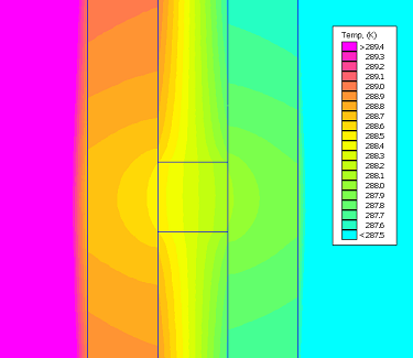
Effect of thermal break on a wall with metal stud framing
The effect of thermal bridging in a precast concrete wall is investigated here. Metal framing studs are attached to concrete and 90mm thick insulation completely fills the space between two consecutive vertical frames. Stud frame depth, width and thickness are 92×33.5×0.75mm respectively with a span of 600mm c/c.
- Ideal Case – this is an unrealistic case and intentionally added for a better comparison.
- Actual Case – with no thermal breaks and full effect of thermal bridging.
- Actual Case – with R0.2 thermal breaks (12mm EPS strips or 20mm piece of timber)
- Actual Case – with R0.4 thermal breaks (25mm EPS strips or 17mm rigid Rockwool)
The results of each case is hereby presented:

Ideal case - no thermal bridging
Click here to to investigate Reference Building model and its assigned building fabric insulation and external glazing thermal performance.
Thermal bridging effect: In this ideal case, no thermal bridging is allowed.
Thermal break: No thermal break.
Total R-value: R3.14
Reduction in Total R-value compared to the ideal case: 0%
Actual case - no thermal break
Click here to to investigate Reference Building model and its assigned building fabric insulation and external glazing thermal performance.
Thermal bridging effect: R1.78 reduced from the Total R-value
Thermal break: No thermal break.
Total R-value: R1.36
Reduction in Total R-value compared to the ideal case: -57%
Actual case - R0.2 thermal break
Click here to to investigate Reference Building model and its assigned building fabric insulation and external glazing thermal performance.
Thermal bridging effect: R0.69 reduced from the Total R-value
Thermal break: R0.2 thermal break
Total R-value: R2.45
Reduction in Total R-value compared to the ideal case: -22%
Actual case - R0.4 thermal break
Click here to to investigate Reference Building model and its assigned building fabric insulation and external glazing thermal performance.
Thermal bridging effect: R0.45 reduced from the Total R-value
Thermal break: R0.4 thermal break
Total R-value: R2.69
Reduction in Total R-value compared to the ideal case: -14%
As can be seen above, a metal stud frame greatly reduces the effectiveness of the added thermal insulation (by more than 57%). The addition of R0.2 thermal breaks saves greatly in terms of energy efficiency. Compared to the case with no thermal breaks, R0.2 thermal breaks increases the wall Total R-value by more than 80%. Also, the addition of R0.4 thermal break almost doubles (more than 97%) the wall Total R-value compared to the case with no thermal breaks. In this case, we have a 14% buffer compared to an ideal case with no thermal bridging effect. As far as metal construction goes, this is almost as good as it gets.
