What are the Common Construction Elements?
Construction elements and their dimensions are crucial in building design. Typically, these elements vary in their type (frame, membrane), material (timber, metal) or application (roof, wall). In this article, we look into the components of roof and wall construction, highlighting the most commonly used dimensions in Australia. We focus on these elements due to their role in thermal bridging and insulation allocation.


Roof Construction Elements
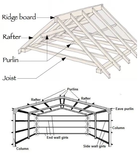
Purlin: the term purlin refers to roof members that are parallel to the walls or eaves. Purlins are required to support the roof sheeting or roof decking and themselves are supported by walls or rafters. The most commonly used steel purlins are Z-shaped 203×79×1.9mm. Purlins generally span from 1.2m to 8m. Insulation sits between purlins in a flat steel-framed roof system with an attached or suspended ceiling. This is typical of a Class 7b building with a conditioned space.
Rafter: the term rafter refers to a sloped structural member that extends from the roof ridge to the wall top plate. Rafters are designed to support the roof deck and its load. The most commonly used timber rafters are 240×35mm with 6000mm c/c. Insulation sits in the gap created by the timber rafters in a cathedral ceiling system.
Joist: the term joist refers to a horizontal structural member used in framing to span an open space. Generally, the longer face of a joist is positioned vertically. Depth of the joist is very important for a stable ceiling system. The wider the spacing between the joists, the deeper the joist will need to be to limit stress and deflection under load. The most commonly used timber joists are 90×35mm with 1200mm c/c. Insulation sits between the timber joists in a pitched roof with a flat ceiling system.

Wall Construction Elements
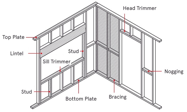
Stud: the term stud refers to a vertical framing member that is part of the wall construction. It is a fundamental element in frame building. Studs could be used just to separate spaces as non-load bearing studs. Studs shape the building envelope and hold windows and doors in place. The most commonly used timber stud wall dimension is 90×45mm @ 450mm or 600mm c/c. Steel framing studs are generally 92×35.5×0.75mm with 600mm c/c. Bulk insulation sits between the gap created by two adjacent studs.
Nogging: the term Nogging refers to a horizontal member of wall construction that runs in parallel with the top and bottom plates and between the studs. Noggings straighten the centre of the wall and provide lateral support to the studs. The number of noggings generally depends on the wall height. For a typical 2.7m high wall, one noggin is installed which contributes to the thermal bridging. Generally have the same size as the wall studs.
Purlins, Rafters and Thermal Performance of Buildings
Purlins, rafters and joists can potentially impact the energy efficiency and thermal performance of a building. When conducting Part J report, JV3 report or ESD report, energy assessors must ensure that thermal bridging through these construction elements is addressed. Energy efficiency reports involve achieving a required Total R-value for roofs, walls and floors. The contribution of purlins and rafters to reducing the Total R-value due to thermal bridging could be significant. Therefore, ESD consultants offer solutions to mitigate the negative effects of thermal bridging through purlins and rafters and to achieve the required Total R-value of building fabric at minimal cost.

Part J of NCC Volume 1, focuses on the energy efficiency of commercial buildings. To obtain a building permit, a Part J report (Section J report) is required for submission. For example, the Performance Requirement for a roof construction of an office in Melbourne, Victoria, is to achieve a Total R-value of 3.2. A typical uninsulated roof in Melbourne has a Total R-value of about 0.5. Does this mean that adding R2.7 insulation would achieve a Total R-value of 3.2, thus meeting the Performance Requirement of the code? the short answer is no. The reason is that the insulation does not actually add R2.7 to the roof. Since it is laid between roof purlins or rafters, thermal bridging reduces the effective R-value. Consequently, the combination of purlins and insulation achieves lower R-values, such as R2.0 or even R1.5.
Typical Purlin and Rafter Sizes
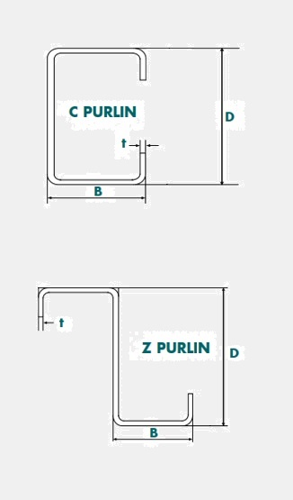
The following table displays typical sizes of C-section and Z-section metal purlins and rafters used in Australia. Note that the lesser the depth and the greater the width and thickness, the more the purlin or rafter contributes to thermal bridging. These section details are used to account for thermal bridging while conducting Part J energy reports and JV3 reports.
| Section | Depth – mm (D) | Width – mm (B) | Thickness – mm (t) |
|---|---|---|---|
| 100-10 | 102 | Z: 53 – C: 51 | 1.0 |
| 100-12 | 102 | Z: 53 – C: 51 | 1.2 |
| 100-15 | 102 | Z: 53 – C: 51 | 1.5 |
| 100-19 | 102 | Z: 53 – C: 51 | 1.9 |
| 150-12 | 152 | Z: 65 – C: 64 | 1.2 |
| 150-15 | 152 | Z: 65 – C: 64 | 1.5 |
| 150-19 | 152 | Z: 65 – C: 64 | 1.9 |
| 200-15 | 203 | Z: 79 – C: 76 | 1.5 |
| 200-19 | 203 | Z: 79 – C: 76 | 1.9 |
| 200-24 | 203 | Z: 79 – C: 76 | 2.4 |
| 250-19 | 254 | Z: 79 – C: 76 | 1.9 |
| 250-24 | 254 | Z: 79 – C: 76 | 2.4 |
| 300-24 | 300 | Z: 100 – C: 96 | 2.4 |
| 300-30 | 300 | Z: 100 – C: 96 | 3.0 |

Performance Requirements for Purlins and Rafters
For a typical dwelling or townhouse, classified as a Class 1a building, adding a thermal break with a minimum R-value of R0.2 is sufficient to meet the Performance Requirements for mitigating thermal bridging. This is a common practice when conducting whether Residential Energy Report or VURB energy report.
For a non-residential building, the NCC requires calculating the Total R-value, including the effects of air gaps and thermal breaks. Unlike residential buildings, a thermal break with an R-value of R0.2 may not be sufficient to meet the Performance Requirements. After accurately calculating the Total R-value and accounting for thermal bridging, you will need to add sufficient insulation or thermal breaks to achieve the required Total R-value for the roof or ceiling.
Typical Metal Stud Sizes
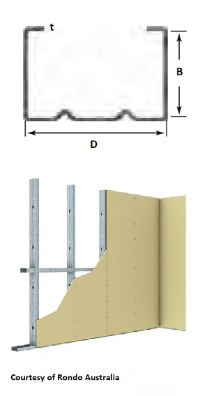
The following table displays typical metal stud sizes used in Australia. Note that the lesser the depth and the greater the width and thickness of the metal stud, the more it contributes to thermal bridging. These section details are used to account for thermal bridging while conducting ESD reports, Section J energy efficiency reports and JV3 Performance Solution Reports.
| Size | Depth – mm (D) | Width – mm (B) | Thickness – mm (t) |
|---|---|---|---|
| 50mm | 51 | 35.5 | 0.5 |
| 50mm | 51 | 35.5 | 0.75 |
| 65mm | 64 | 35.5 | 0.5 |
| 65mm | 64 | 35.5 | 0.75 |
| 65mm | 64 | 36.0 | 1.15 |
| 75mm | 76 | 35.5 | 0.55 |
| 75mm | 76 | 35.5 | 0.75 |
| 75mm | 76 | 36.0 | 1.15 |
| 90mm | 92 | 35.5 | 0.55 |
| 90mm | 92 | 35.5 | 0.75 |
| 90mm | 92 | 36.0 | 1.15 |
| 150mm | 150 | 35.5 | 0.75 |
| 150mm | 150 | 36.0 | 1.15 |

Performance Requirements for Metal Studs
For a typical residential dwelling (Class 1a building), adding a thermal break with a minimum R-value of R0.2 is sufficient to meet the Performance Requirements for mitigating thermal bridging.
For non-residential buildings, just like the case for roof and ceiling, you must calculate the impact of thermal bridging. After calculating the effective Total R-value (after reducing it to account for thermal bridging), you will need to add sufficient insulation or thermal breaks to achieve the required Total R-value.


